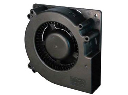


The performance of cross-flow fans (such as air volume, air pressure, efficiency, noise, etc.) is significantly affected by the geometric parameters of the impeller. By optimizing these parameters, the airflow characteristics can be improved, energy loss can be reduced and overall efficiency can be enhanced. The following is an analysis of the key geometric parameters and their impact on performance:
I. Geometric Parameters of Blades
1. Blade installation Angle (β)
Definition: The Angle between the chord of the blade and the tangent of the impeller's circumference.
Impact:
Increasing β : It raises the axial velocity of the airflow, increases the air volume and static pressure, but it may intensify flow separation, leading to a decrease in efficiency and an increase in noise.
Reduce β : Lower wind pressure but improve flow adhesion, suitable for scenarios with low noise requirements.
Optimization range: Usually 20° to 40° (for forward blades), and it is necessary to match the rotational speed and working conditions.
2. Number of leaves (Z)
Impact:
Too many blades (such as (60 pieces) : The airflow channel Narrows, the friction loss increases, the efficiency decreases, and the high-frequency components of the noise increase.
Too few leaves (such as) (30 pieces) : Insufficient air flow filling, resulting in a decrease in air pressure and air volume, may cause pulsating noise.
Empirical formula:
Z≈πDt(t is the blade spacing, usually 1.2 to 1.5 times the blade chord length)Z≈tπD (t is the blade spacing, usually 1.2 to 1.5 times the blade chord length)
Recommended value: 35 to 55 pieces (commonly used in the air conditioning field).
3. Blade Profile
Airfoil selection:
Forward-curved airfoil: Enhances the airflow guidance capacity and increases wind pressure, but it is prone to generating backflow vortices.
Backward-curved airfoil: More stable flow, higher efficiency, but lower wind pressure.
Asymmetric airfoil (such as the NACA series) : Reduces wake vortices and lowers noise.
Thickness ratio: The ratio of the maximum thickness of the blade to the chord length (usually 5% to 12%). If it is too thick, the resistance will increase; if it is too thin, the strength will be insufficient.Ii. Impeller Structure Parameters
1. Impeller diameter (D)
Impact:
Increase D: Enhance the air volume and air pressure (air volume ∝D², air pressure ∝D²·n², where n is the rotational speed), but increase the volume and inertia.
Reduce D: It is suitable for compact designs, but the rotational speed needs to be increased to compensate for wind pressure loss (which may increase noise).
Constraint condition: It needs to match the clearance of the volute (usually the clearance on one side is 1 to 3mm; if it is too large, it will cause leakage vortices).

2. Impeller length (L)
Impact:
Increase L: Directly increase the air volume (approximately linear relationship), but it may cause uneven axial airflow distribution (the volute diversion needs to be optimized).
Shorten L: Reduce air volume but improve the uniformity of end flow.
Length-to-diameter ratio (L/D) : The typical value is 3 to 10. When it is too large, the support stiffness should be considered (to prevent the impeller from deforming).
3. Radial height of the blade (h)
Definition: The radial distance from the tip of the blade to the inner edge of the impeller.
Impact:
Increasing h: It increases the area through which the airflow passes and boosts the air volume, but it may expand the internal vortex zone.
Reduce h: Limit air volume but improve flow concentration.
Design suggestion: h/D ≈ 0.1-0.2, which needs to be highly coordinated with the volute flow channel.
Iii. Interaction Influence of Key Parameters
Consistency (σ = Z·c/πD)
Definition: The ratio of the total chord length of the blade to the circumference of the impeller (c is the chord length of the blade).
Impact:
High consistency (σ>) 1) : Enhance the ability to control the airflow, but increase the friction loss.
Low consistency (σ< 0.8) : The risk of flow separation increases.
Optimization value: 0.9-1.2 (balancing wind pressure and efficiency).
The clearance between the impeller and the volute
Radial clearance: Excessive clearance can cause air leakage and form vortices (it is recommended to be ≤1% of the impeller diameter).
Axial clearance: It affects the smoothness of air intake and exhaust. It is necessary to avoid turbulence caused by sharp edges.
Iv. Performance Optimization Direction
Multi-objective trade-off
For example, increasing the number of blades can enhance the wind pressure, but the blade profile needs to be optimized simultaneously to suppress noise.
CFD Aided Design
The parameter sensitivity is analyzed through numerical simulation, such as:
The influence of the leading edge radius of the blade on the separation vortex.
The inhibitory effect of the shape of the blade tail margin on wake turbulence.
Experimental verification
The actual flow field was observed by using PIV (Particle Image velocimetry) to verify the effect of parameter adjustment.
V. Typical Parameter Combination Examples (Cross-Flow Fans for Household Air Conditioners)
| Parameters | Value range | Performance correlation |
| Impeller diameter(D) | 80~120mm | Basic dimensions of air volume and air pressure |
| Number of leaves(Z) | 35~45slice | Wind pressure and noise equilibrium point |
| Blade installation Angle(β) | 25°~35° | Determine the axial/tangential velocity ratio of the airflow |
| Blade chord length(c) | 15~25mm | Affect consistency and airflow adhesion |
| Length-to-diameter ratio(L/D) | 5~8 | The trade-off between air volume and space constraints |
Summary
The geometric parameters of the cross-flow fan impeller need to be optimized in a coordinated manner. Priority should be given to core parameters such as the installation Angle, quantity, profile of the blades, and the diameter/length of the impeller. Then, the efficiency can be improved by adjusting details such as the clearance and consistency. In the actual design, parameter iteration should be carried out in combination with specific application requirements (such as static pressure requirements and noise limits), and the performance improvement effect should be verified through simulation and experiments.